SMALL SIZE GEM DETECTOR ASSEMBLY

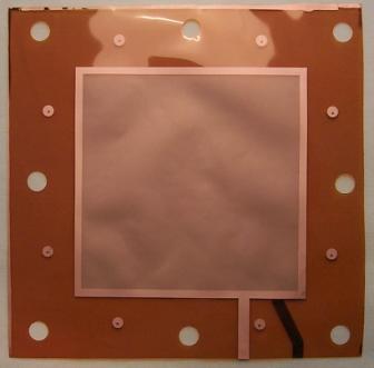 |
A raw GEM foil; the active area is 100x100 mm2, with a 4 mm wide metal strip around edges and two contact leads on opposite sides; the kapton foil outer dimensions are about 150x150 mm2. Holes in the foil can be used for positioning during framing. |
 |
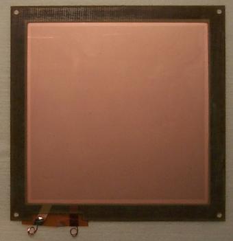
Schematic of a thin (0.5 mm thick) fibreglass frame used to mount GEMs. To avoid warping, two frames are glued symmetricaly on each side of the GEM foil, pre-stretched and cut to size after gluing. |
 |
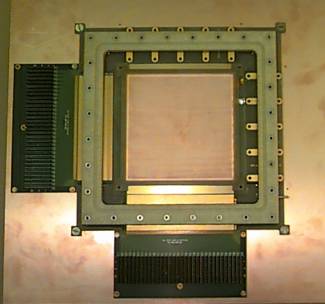
A framed GEM ready for mounting within the box. |
GEM
foils are HV tested before and after framing (requred less than 5 nA at 500
V in dry air). All tests and manipulations should be done in clean room conditions
(class 1000 minimum). Any contact with the active area should be avoided,
including loading with hard surfaces.
